 |
|||||||||||||||
all artwork author's collection, unless otherwise noted |
||
 |
||
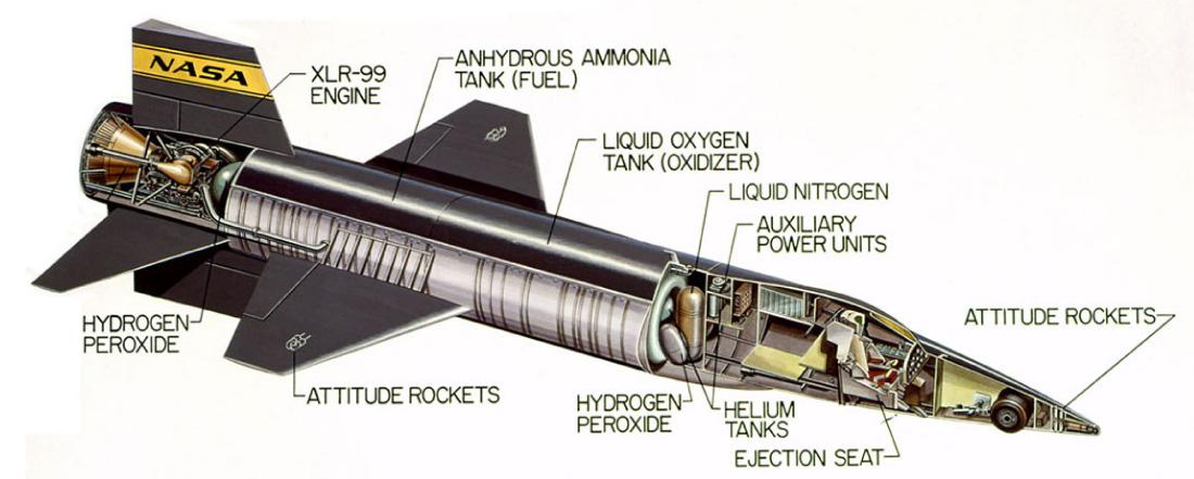
A large poster was produced with callouts of various items and systems on the X-15A-2. |
||
 |
||
Cutaway view of the X-15 with major systems highlighted. North American Aviation |
||
 |
||
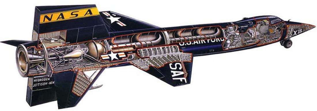
A very detailed interior view of the X-15. |
||
 |
 |
|||
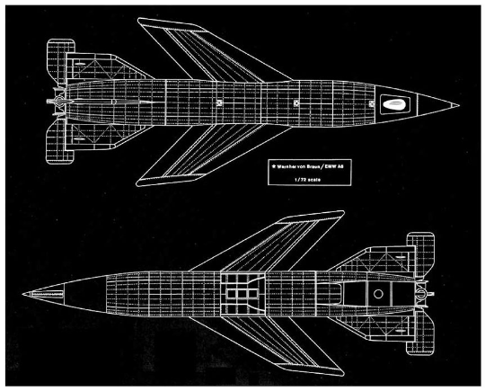
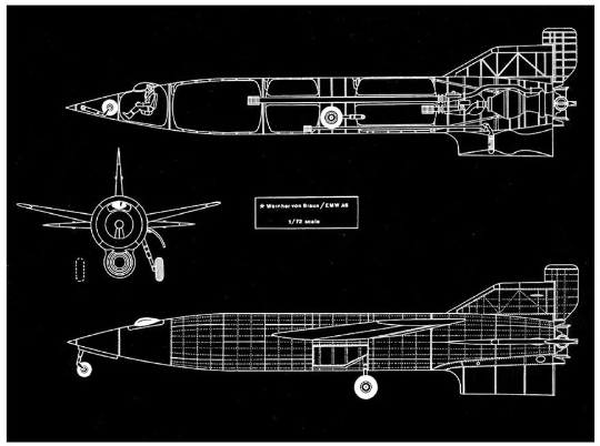
Wernher von Braun designed a manned version of the V-2 (A-4B) that many see as a precursor to the idea of the X-15, flying into space and back again. |
||||
 |
|||||
 |
|||||
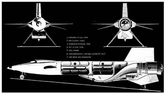
An advanced concept X-15 with a massive scramjet. |
|||||
 |
|||||
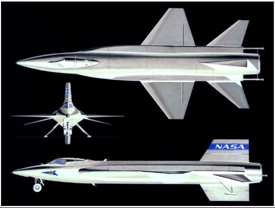
A basic 3-view of the X-15 from NASA. |
|||||
 |
|||||
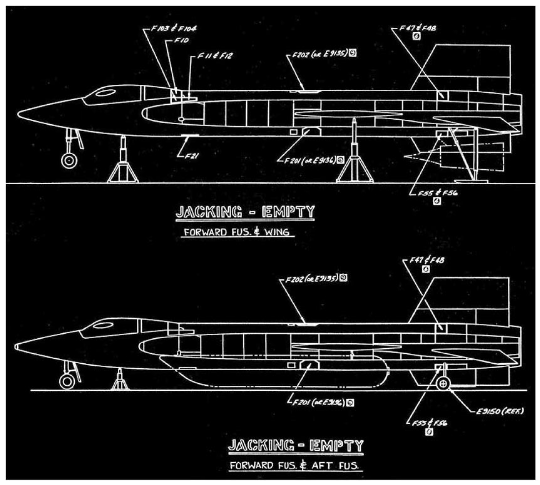
Diagrams showing the proper way of jacking the aircraft safely with no fuel aboard, with and without the external fuel tanks, with the dummy scramjet mounted under the lower ventral fin, and with the landing gear deployed. |
|||||
Details of the X-15 ejection seat. |
||
 |
||
A well-textured 3-view of the X-15A-2 with the external fuel tanks in place. |
||
 |
||
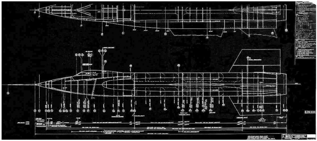
A North American Aviation blueprint showing the fuselage stations of the early X-15 with the nose probe in place. |
||
 |
||
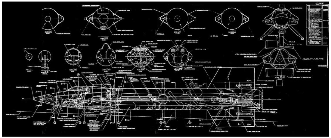
A sectional blueprint of the XLR-99-equipped X-15. |
||
 |
||
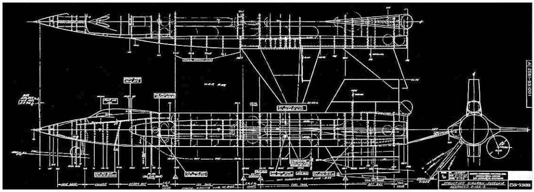
A North American Aviation blueprint showing the fuselage stations of the X-15A-2. Included are the external tanks, tail-mounted pressure vessel, extended landing gear, and dummy scramjet. |
||
 |
||
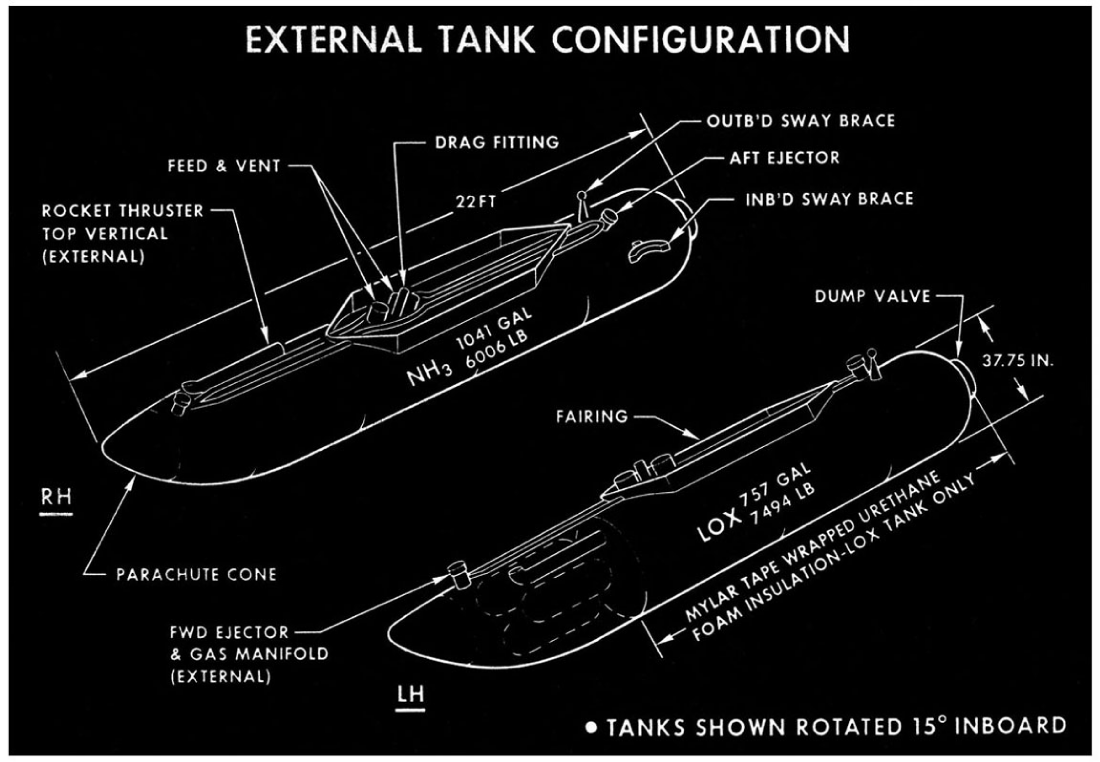
The two external fuel tanks are shown with various components highlighted, such as the fuel and oxidizer lines, mounting fairing, and ejection thrusters. |
||
 |
||
Marking placement schematic for an external fuel tank. |
||
 |
 |
|||
Diagram showing the proper way to hoist an empty X-15. |
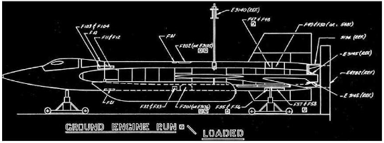
The X-15A-2 with external tanks mounted in the PSTS for a static engine firing test. |
|||
 |
 |
|||
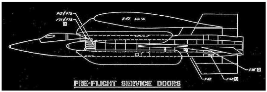
Location of pre-flight service doors on the X-15A-2 for access while already mounted to the B-52's wing pylon. |
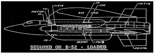
Diagram showing servicing doors for the X-15A-2 once securely mounted to the B-52 wing pylon and fueled, ready for take-off. |
|||
 |
||
Extremely detailed cutaway image of the X-15A-2. |
||
 |
||
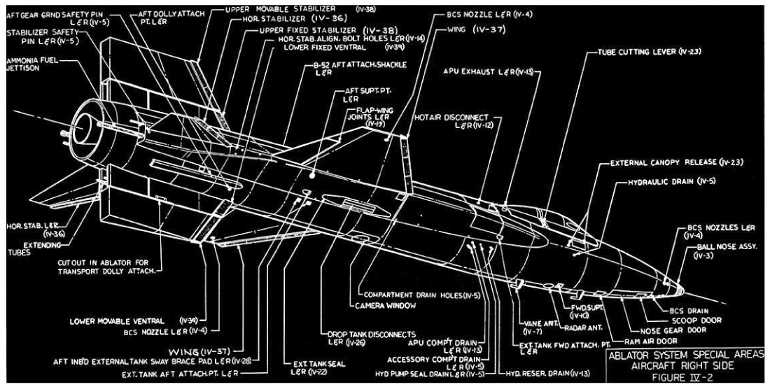
Two views of the X-15 showing detailed positions of specific important pieces on the exterior of the X-15. Left side above and right side below. |
||
 |
||
 |
||
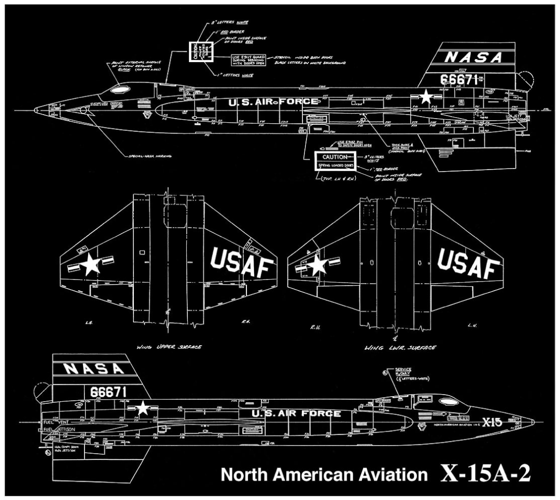
Schematic showing the locations of the various markings to be added to the surfaces of the fuselage, wings, and tail of the X-15A-2. |
||