 |
|||||||||||||||
 |
 |
|||
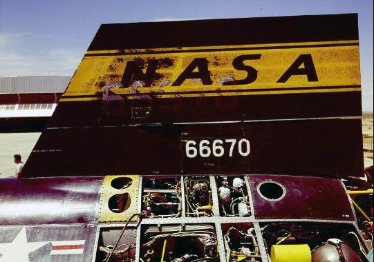
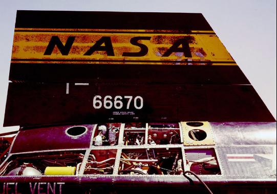
Left and right surfaces of the upper vertical stabilizer of X-15 no. 1 following an early NASA flight. Note all the access panels removed for servicing and inspection. author's collection |
||
 |
 |
||||
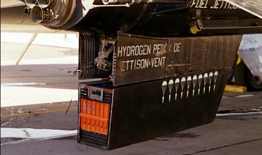
Close-up on lower ventral. Note the parachute markings to designate that it has been reflown successfully ten times prior to this flight. author's collection |
|||||
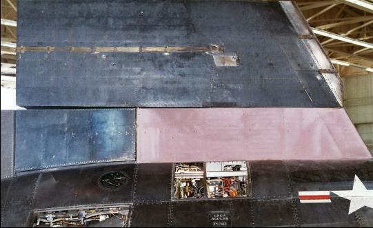
X-15 no. 3 right-side vertical tail ablative test sample (pink area) flown on 23 Apr. 1965. Armstrong Flight Research Center |
|||||
 |
 |
|||
A technician uses a Mobile Internal System Test Equipment Rack for X-15 check-out. North American Aviation |
X-15 operations required hydrogen peroxide, a dangerous substance to handle. North American Aviation |
|||
 |
 |
|||
Technicians attach the transport dolly to the rear of the X-15. TD Barnes collection |
Forward ballistic control system rockets installed in the nose of the X-15. Armstrong Flight Research Center |
|||
 |
 |
|||
Rear view of the lower ventral speed breaks in the open position. author's collection |
Front view of the upper ventral speed breaks open on X-15 no. 3 in the NASA hangar. author's collection |
|||
 |
 |
|||
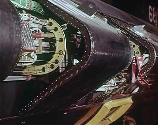
Access panels removed from the fuselage fairing along the left side of an X-15. NASA Headquarters |
X-15 no. 3, with wiring connectors hanging out of the instrumentation bay. author's collection |
|||
 |
 |
|||
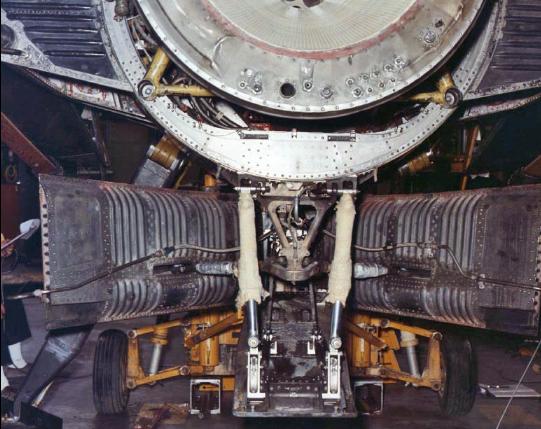
The left rear skid shown deployed after landing. Armstrong Flight Research Center |
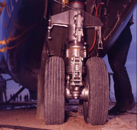
The dual-wheel nose gear and oleo assembly. Armstrong Flight Research Center |
|||
 |
 |
||||
A third skid was installed between the lower ventral speed brakes on X-15 no. 1. This was flown by Michael Adams on Mission 1-71-121 on 28 Apr. 1967. Armstrong Flight Research Center |
|||||
Helium pressure vessel installed in the rear fuselage of the X-15A-2 on 5 Mar. 1965. Armstrong Flight Research Center |
|||||
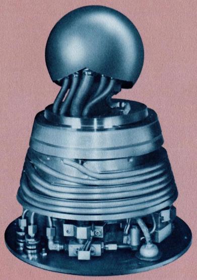
— The Nortronics "Q" Ball Attitude Sensor — |
||
Nortronics, the electronic development division of the Northrop Corporation, developed the Flight Path Control Sensor for use on the X-15. More simply, it was known as the "Q Ball" because it sensed dynamic air pressure, known as Q in aeronautical terms. That measurement of Q by the sensor told the X-15 which direction it was flying, especially important for angle-of-attack during re-entry. The sensor was literally the nose cone of the X-15. |
||
 |
 |
|||
The Nortronics Flight Path Control Sensor design team. On the right is shown a clear-view model of the Q-Ball, while on the left is an actual finished sensor instrument. Bob Hayos, Nortronics |
||
 |
 |
|||||
Dave Graham, in charge of Northrop's wind tunnel, and EC Welch, head of Nortronics Control System Development, ready the Q-Ball for low flow sensitivity tests. Bob Hayos, Nortronics |
||||||
Nortronics engineers David Ruch and George Mills in the wind tunnel with the Q-Ball. Bob Hayos, Nortronics |
||||||
 |
 |
|||||
Al Vogel of the Servo-Electronics section and David Ruch of the Wind Tunnel crew. Bob Hayos, Nortronics |
||||||
Someone got the idea to display a completed X-15 Q Ball and housing next to pool balls. Bob Hayos, Nortronics |
||||||
 |
 |
|||
The Q Ball sensor package installed on the front of the X-15. Wires come out of an access panel for testing. Bob Hayos, Nortronics |
A Nortronics Q Ball publicity illustration. Bob Hayos, Nortronics |
|||
 |
 |
|||
The Flight Path Control Sensor housing under construction on a milling machine. Bob Hayos, Nortronics |
Neil Armstrong flew the first X-15 mission using the Q Ball sensor. Armstrong Flight Research Center |
|||
— Examples of Experiments Carried Aloft by the X-15 — |
||
 |
 |
|||
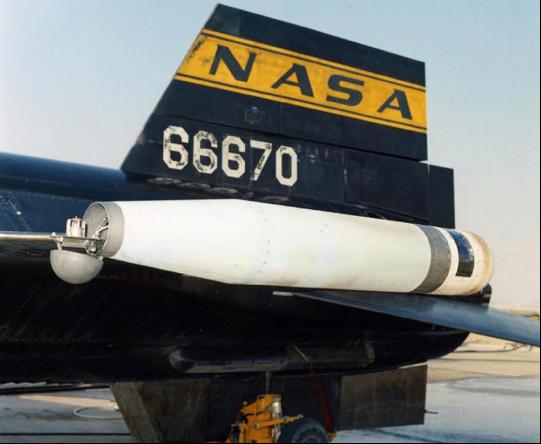
The Western Test Range (WTR) experiment extended up out of an access hatch behind the cockpit called the "skylight." It was used to track a missile launched from Vandenberg AFB. Photographed on 2 Aug. 1966. Bill Dana would fly this experiment on Mission 3-53-79 on 4 August to 132,700 feet at Mach 5.34 or 3,693 mph. TD Barnes collection |
||
 |
 |
|||
WTR experiment installed in X-15 no. 3 on 2 Aug. 1966, with access cover removed. Armstrong Flight Research Center |
The WTR experiment stowed with the skylight hatch opened. Armstrong Flight Research Center |
|||
 |
 |
|||
Left-hand wingtip pod with cap open and experiment mount extended. Armstrong Flight Research Center |
The same pod after a hypersonic flight on the tip of X-15 no. 1's wing. Armstrong Flight Research Center |
|||
 |
||
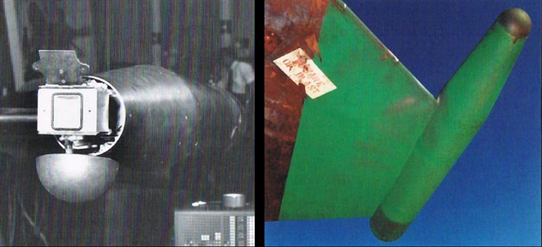
The Atmospheric Density Measurement experiment. The sensor is shown deployed in the image at left, while the pod, covered in green thermopaint is shown on the right. author's collection |
||
 |
 |
|||
The Jet Propulsion Laboratory Solar Spectrum experiment carried in the rear of the wing-tip pod. On the left it is undergoing testing, and at right, is installed in the rear of the pod. Armstrong Flight Research Center |
||
 |
 |
|||
The X-15 with tip pods is mounted to the B-52 pylon. Note the small clearance between the left wingtip pod and the B-52s fuselage. Image taken 13 Sep. 1966, prior to Mission 3-55-82 which will be flown by Bill Dana the following day. TD Barnes collection |
||||
A wing tip pod experiment under test. TD Barnes collection |
||||
 |
 |
|||
A test was devised to mount a section of insulation, to be used on upcoming Saturn V missions, to the upper left side speed brake of X-15 no. 3. The insulation would be exposed to hypersonic speeds and heating effects when the speed brake was deployed during flight. TD Barnes collection |
||
 |
 |
|||
The camera ports for the KS-25 on the bottom fuselage of X-15 no. 1. Robert Rushworth flew this on Mission 1-45-72 on 27 Mar. 1964. Armstrong Flight Research Center |
||||
The KS-25 reconnaissance camera installed in the X-15 instrumentation bay. author's collection |
||||
 |
 |
|||
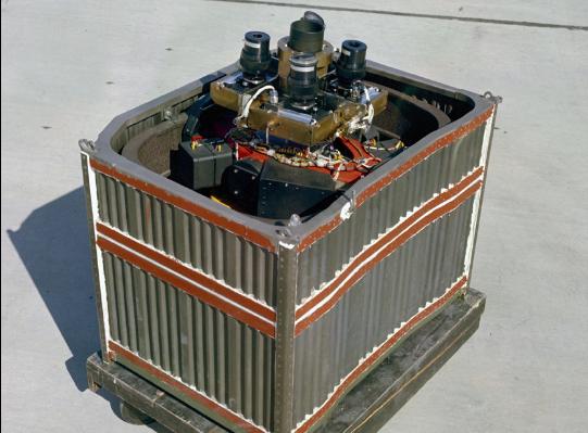
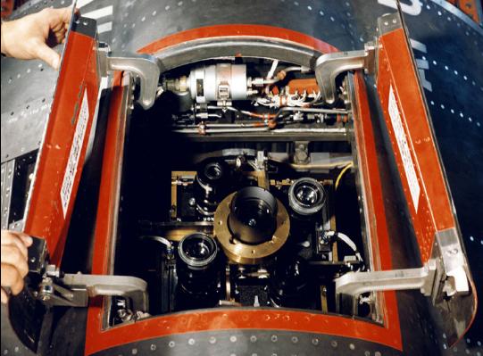
A Star Tracker system was flown by Pete Knight on Mission 2-47-84 on 3 Aug. 1966. The instrument was constructed by the University of Wisconsin's Washburn Observatory. It photographed stars from 249,000 feet while flying at Mach 5.03 or 3,440 mph. At left is the experiment before installation in the X-15A-2. At right is after installation. Armstrong Flight Research Center |
||
 |
 |
|||
The Rarified Wake Flow experiment deployed a Mylar balloon for photography. Joe Walker unsuccessfully attempted this on Mission 3-21-32 on 19 Jul. 1963. author's collection |
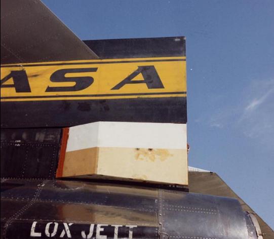
Like the Wake Flow experiment, this Horizon Definition infrared experiment from NASA Langley was installed in a box at the rear of the X-15 no. 3 upper vertical tail. author's collection |
|||
 |
A proposal was made to use the X-15 as a launch platform for a Blue Scout rocket, which could put small satellites into Earth orbit. Launch was accomplished by extending a rail from the bottom of the X-15 fuselage. The idea got as far as wind tunnel models, but no hardware was manufactured. The idea was used in the book "Mike Mars, South Pole Spaceman." author's collection |
|||||
 |
||||||
X-15 wind tunnel model with a Blue Scout booster. The nose of the rocket was an ASSET vehicle. author's collection |
||||||